
Chapter 8 of the VisualXSL User Guide
7. Examples
7.1. Example of Creating XML Source and PDF Background
For this example Microsoft Office Professional Edition 2003 (or later) must be installed.
You can use Microsoft Excel to prepare an XML source file and Microsoft Word to make an invitation letter form.
In this example, you prepare and mail an anniversary party invitations to all company managers named CEO. All employees’ information is stored in an Excel spreadsheet (see Figure 7.1 below). The letter should look like the one in the figure below, and you should be able to print it or Email it as an electronic document.
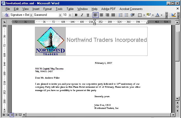
Figure 7.1. Invitation letter

Figure 7.2. Data in the Excel spreadsheet
First of all, create the XML source file. You should have an XML schema to be able to map the data to the XML tags and export it to an XML file. The simplest way to do that is to prepare a small XML file describing the common structure of your data.
The XML file should look like the following example (you can omit any elements not necessary for your task). You should write the XML node corresponding to the data record twice to make Microsoft Excel realize that this node can be replicated many times.
Attach a new XML map by doing the following:
-
Open the XML Source tab by selecting Data | XML | XML Source.
-
Click the XML maps button, which opens the window with the XML map list.
-
Add a new file by clicking the Add button and selecting a prepared XML file as an XML source.
-
When a warning message appears saying that no XML schema is referred to this file, click OK.
Excel creates the schema automatically.
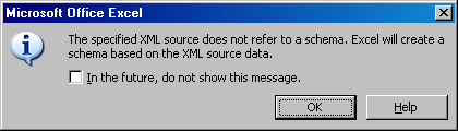
Figure 7.3. Warning that Microsoft Excel will create a schema based on selected XML file.
-
Map all XML elements to the spreadsheet data columns, you can see the instructions in the bottom of the XML Source tab. After you have finished, you can export the spreadsheet to XML.
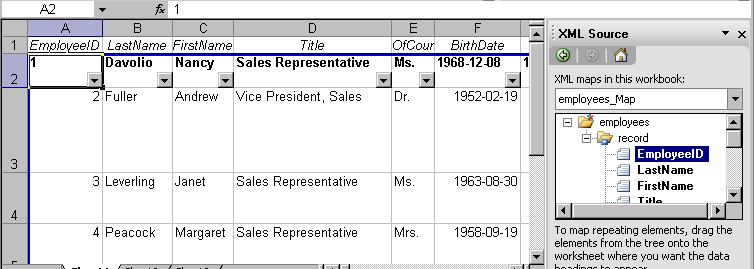
Figure 7.4. XML elements mapped to Microsoft Excel spreadsheet data columns
-
Save your spreadsheet as an XML file to your project folder.
-
To prepare a PDF document that can be used as a background, you can use Microsoft Word and create a document with space left for variable data. The document might look like the following
Figure 7.5. Save it as an XML (WordML) file.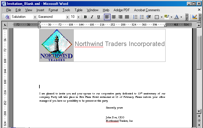
Figure 7.5. Letter with space left for employee personal data
-
Use IREn Assistant and WordML2FO stylesheets from the XEPWin package to produce a PDF file from your mockup.
With the XML source file and the PDF file, you have the files necessary for creating a new project.
7.2. Example of Exporting XML Data File from SQL Server
For this example we use the Northwind test database and Query Analyzer (Microsoft SQL Server 2000) for the data conversion.
-
Open SQL Query Analyzer(Microsoft SQL Server 2000).
-
Connect to the
Northwinddatabase.Our goal is to convert data from the
Employeestable.
Figure 7.6. Data in the Employees table
-
Assume that the file with the converted data should be placed under
c:\temp\. -
Using any text editor (for example
Notepad), create thetemplate.tplconversion template file in this folder. -
Use the editor to enter the following in this template file:
<root> <%begindetail%> <%insert_data_here%> <%enddetail%> </root> -
Enter the following query into the
SQL Query Analyzerwindow (see the following figure)EXEC sp_makewebtask @outputfile = 'c:\temp\myxmlfile.xml', @query = 'select * from Employees for xml auto', @templatefile = 'c:\temp\template.tpl'where:
-
@outputfile- the full path to file XML. -
@query– thesql queryfor the necessary data. -
@templatefile- a file template to use for creating the XML file.
-
-
Run the query by pressing F5 or by selecting Query | Execute from the menu.
The
myxmlfile.xmlfile is created in thec:\temp\folder.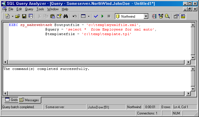
Figure 7.7. Query to export table data
-
The Employees table data is exported to XML format.
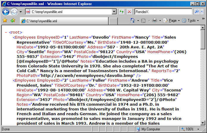
Figure 7.8. Resulting XML file
-
Continue to next sample to build a VisualXSL document.
7.3. Example of Using Radio Buttons
When creating fillable PDF forms, you may need to be able to add radio buttons in your form. Unlike check boxes, radio buttons are grouped so that only one of them can be selected at a time. Creating radio buttons in VisualXSL is similar to creating checkboxes; the only difference is that the Test property of these elements must have the same variable name in their XPath expressions (but different values to compare with). Another way to create Radio Buttons is to give the same Group Name for all Checkboxes.
Note: Radio Buttons are created only if their
Treat as Fieldproperty is settrue.
This example assumes you are starting from an existing project. To start a new project, see Creating a New VisualXSL Project and How to Create a New Project.
Prepare a number of reports in W9 form from existing data (in the C:\Documents and Settings\All Users\Documents\VisualXSL Projects\W9 folder. A sample PDF file with a W9 form (for the background) and an XML file from the database already exist.) For information about preparing an XML source and PDF background, see Example of Creating XML Source and PDF Background and Example of Exporting XML Data File from SQL Server.
7.4. Example of Building a VisualXSL Project(W9 form)
This example assumes you are starting from an existing project. To start a new project, see Creating a New VisualXSL Project and How to Create a New Project.
The example covers the design and publishing of documents based on the US Government W9 form from existing data in the
..\All Users\Shared Documents\VisualXSL Projects\samples\W9 folder
or
..\Users\Public\Public Documents\VisualXSL Projects\Samples\W9 folder.
A sample PDF file with a W9 form (for the background) and an XML file from the database already exist. For information about preparing an XML source and PDF background, see Example of Creating XML Source and PDF Background and in Example of Exporting XML Data File from SQL Server.
Procedure 7.1. To build a VisualXSL project
-
Create a new folder in
C:\Documents and Settings\All Users\Documents\VisualXSL Projectsfor the project and call it. -
Copy the
w9src.xmlandw9_blank.pdffiles from theC:\Documents and Settings\All Users\Documents\VisualXSL Projectsto the new folder. -
Open the
w9src.xmlwith an XML Editor or WordPad (not Notepad) to study its content. Note the XML declarationxml version="1.0" encoding="utf-8", a good practice for it to exist, and with the correct encoding value. Note the XML elementbatchat the beginning andbatchat the end of the file. A top level XML element as noted is required by VisualXSL even if only one set of XML children elements exist. -
Open the
w9_blank.pdfwith Adobe Reader, or equivalent, to become familiar with its content and the various "blank" fields. Close and Exit Adobe Reader. -
Double-click the VisualXSL
 icon on your desktop.
The VisualXSL application opens.
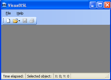
Figure 7.9. Empty VisualXSL application
-
Click the New Project
 button.
The New Project wizard opens.
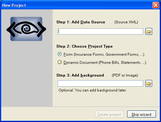
Figure 7.10. New Project wizard
-
Add the data source.
Under
Step 1 : Add Data Sourceclick the Open button, navigate to the
 ..\VisualXSL Projects\Samples\myw9new folder and select thew9src.xmlfile.Note: Alternatively, you can skip the wizard, and add the data source later by using the File | Open Source XML menu to select the
w9src.xmlfile from the newly created folder.Step 2 : Choose Project TypeForm (Insurance Forms, Government Forms,...) for this project the default selection is correct because in the next procedure we will choose a PDF background that is a Form. -
Add the background (PDF or image).
Under
Step 3click the Open button ,navigate to the ..\VisualXSL Projects\Samples\myw9new folder and select thew9src.xmlfile.Note that this step automatically set the BackgroundPath and RasterizedPath property (under Properties | Layout).
-
Click the Create Project button. The new project, yet unnamed, opens in VisualXSL.
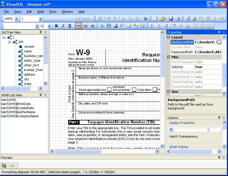
Figure 7.11. New project page
-
Click File | Save as, and save the project as
1stTry.vxl. -
Click in the Layout (the Designer). The page properties are shown in the Properties pane.
-
If you skipped
Step 6, add the background now. In the Properties | Layout, select the BackgroundPath property, click the button, and open the
 w9_blank.pdffile.Note: The application automatically rasterizes PDFs into a PNG image with a filename as noted in the Properties | Layout|RasterizedPath property. This Raster image is used as the document background in the Layout (Designer Area).
-
In the XML Tree View pane, find the
namenode, and drag-and-drop it to the Layout. Place it, and resize the name data field to fit the template in the background form. -
Change the selected data field's properties by clicking in the Properties pane.
Expand the Appearance property, and then the TextProperties property group. You can change the font settings for the selected data field by clicking the
button, and making desired changes in the Fontdialog box toArial, 10pt.Note: Alternatively , you can select the
Font sizethrough the toolbar. Because you are going to add data fields with the same formatting, change the section formatting properties ( Appearance | TextProperties | Font)
Note: To do so move the cursor to an area in Layout away from any fields and select (left mouse button )- see Figure 7.12 below for suggested location shown as

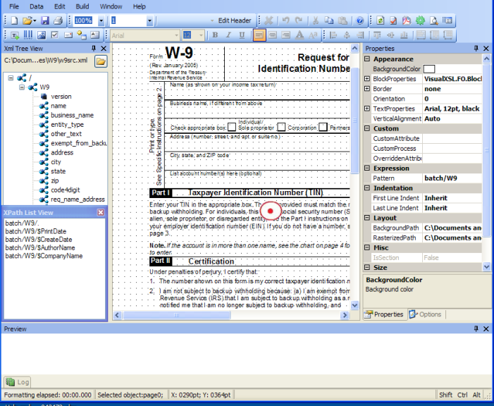
Figure 7.12. Text formatting properties of the selected data field
-
To view a preview of the project at this stage, click the Preview Result of XSLT button in the toolbar.

The Log pane you can monitor the formatting process by tracing messages from the IREn formatter. When the IREn formatter finishes, the Preview pane shows the resulting document. You may now see how the field is placed on the page.
The Log may report a "[Warning]The project page 2 has no frames. It may be rendered not properly." message. This simply means that your document contains a page on which no XML node is rendered. The original US Government W9 form consist of four pages of which page 2 through 4 consist of instructions.
Caution: Click
 to save the project.
Note: By default, to generate a preview only the first three records from the XML are used. You may change this behavior via the Options pane. Be advised that increasing number of records reduces processing of preview, so it is only recommended if your data records vary significantly.
-
Drag-and-drop the rest of the XML nodes to the Layout (note that same are purposely not listed at this time ): business_name, address, city, req_name_address, account_number, soc_sec_number and empl_ident_number and resize them to fit the empty spaces on the background.
Note: To align the Business_Name, Address, City and list account number(s) fields to be left aligned with the Name field:
- Select the Name field. While
Ctrl-key is depressed select the Business Name, Address, City and list account number(s) fields. Release theCtrl-key. Click on theAlign Leftsbutton.

Note: To size the Name and Business Name fields to be the same width and height:
- Select the Name field. While
Ctrl-key is depressed select the Business Name field. Release theCtrl-key. Click on theMake Same Sizebutton.

- Select the Name field. While
-
The address must be correctly formed from the
city,stateandZIPvalues. Select thecityfield and change the Expression|XPathValue property to:concat (city/.,', ',state/.,' ',zip/.,'-',code4digit/.)The XSLT code is generated in the template with the
match="batch/W9"attribute and data acquisition is rendered by the concat (city/.,', ',state/.,' ',zip/.,'-',code4digit/.)XPath expressionNote: The
concatfunction returns the concatenation of its arguments. The string arguments are separated by a comma. Additional strings, like the comma and space betweencityandstate, the space betweenstatezip,and the dash (-)betweenzip `` code4digitare between single (')quotes. -
The Social security number(soc_sec_number) data field should be justified. To set the proper spacing between digits, select the soc_sec_number field and change the BlockProperties|AlignmentLast property value tojustify. -
Repeat the procedure above for the Employer identification number (empl_edent_number) including changing the BlockProperties|AlignmentLast property value to
justify.Note: To view a preview of the project at this stage , click Preview Result of XSLT
 button. Adjust the location(Left and Top ) of all fields.
- Select a field and use the Up, Down, Left or Right arrow keys. The field moves several points (px)based on Grid size defined in the Options panel, irrespective if Snap to Grid is selected or not, or
- Select a field, and while the
Alt-keyis depressed us the Up, Down, Left or Right arrow keys. You will note that the field moves a fraction (0.75px)irrespective of the Grid size defined and if Snap to Grid in the Options panel is selected or not, or
- Select the field and edit the Location|Top and location|Left values in the Options panel. The field moves irrespective of the Grid size defined and if Snap to Grid in the Options panel is selected or not.
Caution: Click
to save the project. -
Place check marks on the appropriate background check boxes so that they are rendered only under certain conditions, according to the XPath expression results.
Select the entity_type XML node in the XML Tree View pane. From the Data menu select Add Checkbox.
Select the check murk just placed in Layout and drag it into the Individual/Sole proprietor check box
- Check appropriate box;
 Individual/Sole proprietor.
While still selected view the value displayed in the expression|test property. It should read
entity_type/.='individual'.if not, changed it. This is the XPath expression used as the condition to render the field. That is, the field is rendered only if this condition is true. - Check appropriate box;
-
Repeat the procedure above for the remaining check boxes, setting the Expression|Test property accordingly as in:
entity_type = 'corporation',entity_type = 'partnership',entity_type = 'limited',entity_type = 'other'.Note: An alternative is to:
- Select the first check mark and
copyonce andpastfour times using one of the actions available.
- Select and drag each check mark into each check box , and set the Expression|Test property accordingly as noted above.
Note: To view a preview of the project at this stage , click Preview Result of XSLT
button. - Select the first check mark and
-
In the XML Tree View pane, find the
other_textnode, select and drag-and-drop it to the Layout here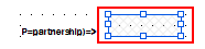 which is associated with the Limited liability company check box.
While still selected view the value displayed in the
Expression|XPathValueproperty. It Should readother_text/.If not, change it.Caution: Define a condition when to render the value which is only applicable when the Limited liability company check box is checked. Set the
Expression| Testproperty toentity_type/.='limited'.This is the XPath expression used as the condition to render the field. That is, the field is rendered only if this condition is true. If not, change it. This is the XPath expression used as the condition to render the field. That is, the field is rendered only if this condition is true. -
In the XML Tree View pane, find the
other_text/node, select and drag-and-drop it to the Layout here which is associated with the Other check box. Place it, and resize the other data field to fit the template in the background form.
While still selected view the value displayed in the
Expression|XPathValueproperty. It Should readother_text/.If not,change it.Caution: Define a condition when to render the value which is only applicable when the Other (see instructions) check box is checked. Set the
Expression| Testproperty toentity_type/.='other'.This is the XPath expression used as the condition to render the field. That is, the field is rendered only if this condition is true. -
Select the
exempt_from_backupXML node in the XML Tree View pane. FromDatamenu selectAdd Checkbox.While still selected view the value displayed in the
Expression| Testproperty. It should readexempt_from_backup/.='true'.This is the XPath expression used as the condition to render the field. That is, the field is rendered only if this condition is true. -
To view a preview of the project at this stage , click Preview Result of XSLT
button. Adjust the location of all fields.Caution: Click
to save the project. -
After all data fields are added and aligned you can generate the XSL stylesheet and/or the resulting PDF document.
Click
 to generate the XSL stylesheet.
Click
 to generate the resulting PDF document, enter a filename and save.
Review the XSL stylsheet and PDF generated.
-
A preliminary view of the project should look similar to that of W9 sample project (except those
Barcodedata fields). SeeFigure 7.13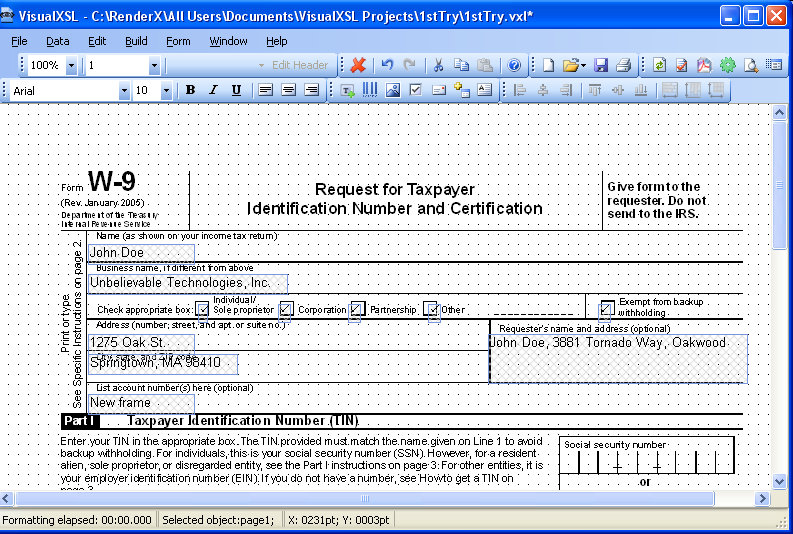
Figure 7.13. View of unfinished project
Congratulations, you have completed one of many VisualXSL projects.
7.5. Example of Building a VisualXSL Project (ICW form)
This example assumes you are starting from an existing project. To start a new project, see Creating a New VisualXSL Project and How to Create a New Project.
The example covers the design and publishing of documents based on the ICW form from existing data in the
..\All Users\Shared Documents\VisualXSL Projects\samples\ICW folder
or
..\Users\Public\Public Documents\VisualXSL Projects\Samples\ICW folder.
A sample PDF file with a ICW form and an XML file from the database already exist. For information about preparing an XML source and PDF background, see Example of Creating XML Source and PDF Background and in Example of Exporting XML Data File from SQL Server.
Procedure 7.2. To build a Dynamic type of VisualXSL project
-
Create a new folder in
C:\Documents and Settings\All Users\Documents\VisualXSL Projects\my ICWfor the project and call it. -
Copy the
ICW.xmlandImagesfolder files from theC:\Documents and Settings\All Users\Documents\VisualXSL Projectsto the new folder. -
Open the
ICW.xmlwith an XML Editor or WordPad or Notepad with "Word Wrap" option enabled to study its content. Note the XML declarationxml version="1.0" encoding="utf-8", a good practice for it to exist, and with the correct encoding value. Note the XML elementbatchat the beginning andbatchat the end of the file. A top level XML element as noted is required by VisualXSL even if only one set of XML children elements exist. -
Open the
w9_blank.pdfwith Adobe Reader, or equivalent, to become familiar with its content and the various "blank" fields. Close and Exit Adobe Reader. -
Double-click the VisualXSL
icon on your desktop.The VisualXSL application opens.
Figure 7.14. Empty VisualXSL application
-
Click the New Project
button.The New Project wizard opens.
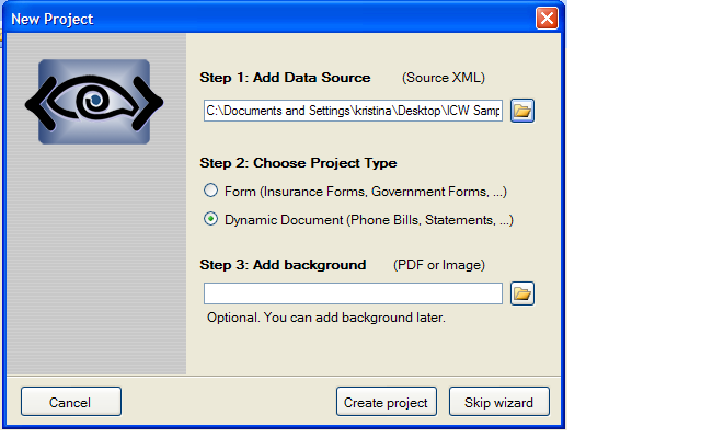
Figure 7.15. New Project wizard
-
Add the data source.
Under
Step 1 : Add Data Sourceclick the Open button, navigate to the ..\VisualXSL Projects\Samples\ICWnew folder and select theICW.xmlfile.Note: Alternatively, you can skip the wizard, and add the data source later by using the File | Open Source XML menu to select the
ICW.xmlfile from the newly created folder.Step 2 : Choose Project TypeDynamic document(phone bills, statements) -
Under
Step 3click the Open button ,navigate to the ..\VisualXSL Projects\Samples\ICWnew folder and select theICW.xmlfile.Note that this step automatically set the BackgroundPath and RasterizedPath property (under Properties | Layout).
-
Click the Create Project button. The new project, yet unnamed, opens in VisualXSL.
-
Click File | Save as, and save the project as
2ndTry.vxl. -
Click in the Layout (the Designer). The page properties are shown in the Properties pane.
-
To Create a header select
Edit header button in the tool bar.
You can manually arrange items in the desire place on the field.
-
In the XML Tree View pane, find the
namenode, and drag-and-drop it to the Layout. Place it, and resize the name data field to fit the template in the background form. -
Change the selected data field's properties by clicking in the Properties pane.
-
Add Image(add rx-logo.png from
imagesfolder ),in the Data menu select Add Image , and in the Properties pane, under Data selectImageUrl.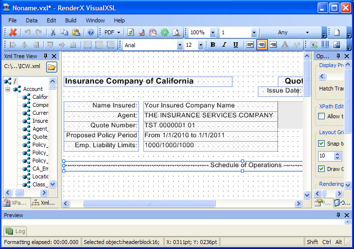
Figure 7.16. Creating a Header
-
Unselect Edit Header.
-
Edit Items.
The Items will dynamically be arranged by turns on the layout.
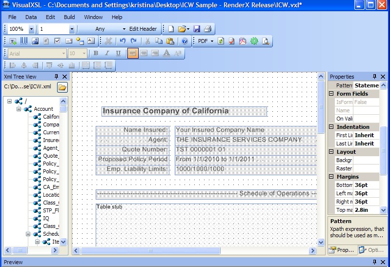
Figure 7.17. Dynamic document
-
in the Properties|Space|Spaces before Area or Spaces after Area
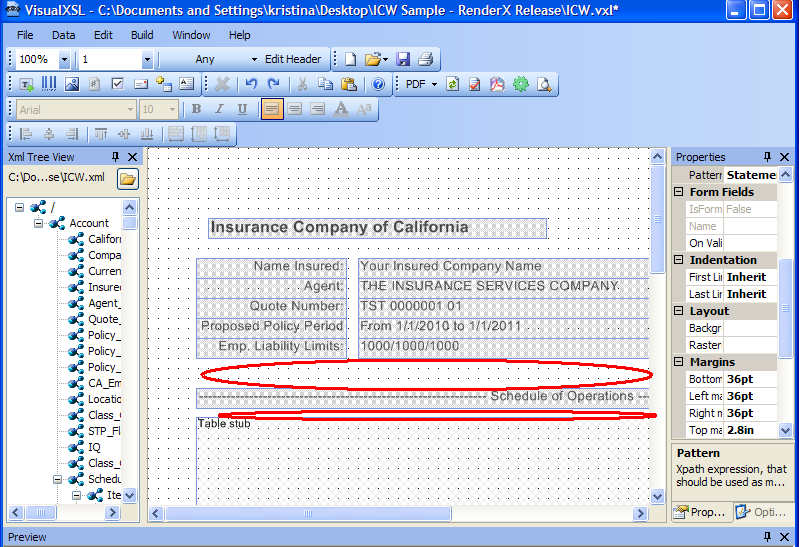
Figure 7.18. Spaces between the items
-
To preview the project at this stage, click the Preview Result of XSLT button in the toolbar.
The Log pane helps you to monitor formatting process by tracing messages from the IREn formatter. When the IREn formatter finishes, the Preview pane shows the resulting document. You may now see how the field is placed on the page.
Caution: Click
to save the project.You can find other instructions at To build a VisualXSL project
7.6. Example of Using IREn and SVG Files As Image
VisualXSL supports using both IREn intermediate format files and SVG graphics files as images. The technique is the same for both IREn intermediate format and SVG files. We illustrate using IREn file; for SVG file the scenario is similar.
Procedure 7.3. To use .IREn file as an image
-
In the
Samplefolder, open theFRUITS.pngfile.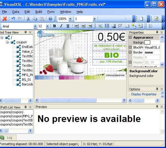
Figure 7.19. Adding an Image
-
In the Data menu select Add Image, and in the Properties pane, under Data, select
ImageUrl.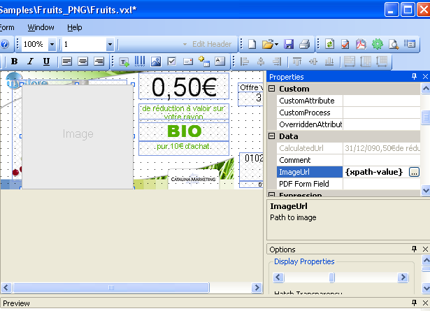
Figure 7.20. After Adding an Image and Selecting the
ImageUrlField -
In
ImageUrl, select the button; the following dialog box appears.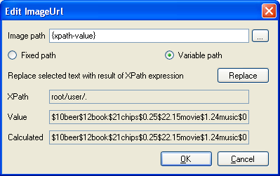
Figure 7.21. Edit ImageUrl dialog box
-
Select
Fixed Pathand viaImage pathfield browse to and selectFruits_PNG/Images/VisualXSL/Lady_Red.xepfile. It may be necessary to changeFiles of type:in the file browser window, in order to show .IREn files. -
In the Edit ImageUrl dialog box, click OK; the dialog box closes, and the
Image pathin the Edit ImageUrl window and theImageUrlin the Properties pane are setLady_Red.xep.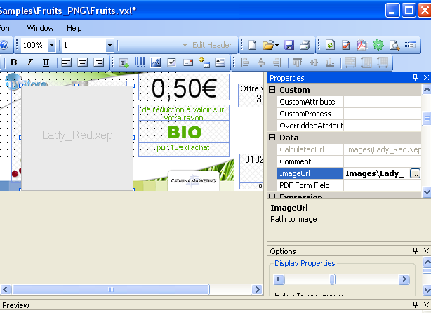
Figure 7.22. Lady_Red.xep has been selected for the new image
-
To see the
Lady_Red.xepimage, in the Build menu you can click Preview; after completion,Lady_Red.xepis visible below in the Preview pane.
7.7. Example of Using Templates
For information about dynamic flows, see How to Create Dynamic Templates section.
In the Samples folder, open the Diners (Credit Card) Statement file.
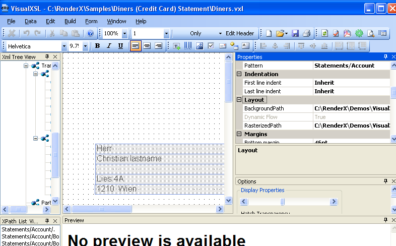
Figure 7.23. Diners (Credit Card) Statement file
In Choose Section Template, the template Only is shown. note the properties values, in the Layout and Margins property groups.
In Choose Section Template, change from template Only to First, Last and Any, and notice that the values in the Properties pane are changed.
For an example of how the templates work together, see the Diners_Sample_by_RenderX.pdf file. The templates that are used for each statement are determined by VisualXSL, according to how many sections of data are to be presented for that statement.
7.8. Example of Using Custom Attributes
VisualXSL now supports three custom attributes properties (that is, attributes not yet natively supported by VisualXSL) for any object type. These properties (CustomAttribute, OverriddenAttribute and CustomProcess) are described in the Data Fields and Properties chapter.
The following is an example of using CustomAttribute and OverriddenAttribute:
Procedure 7.4. To use custom attributes
-
In the
Samplesfolder, open theCustomAttributesfile.Note: All of the borders of the rectangle are the same -
4pt solid cyan. We will use custom properties to access the FO style attributes for the individual border sides.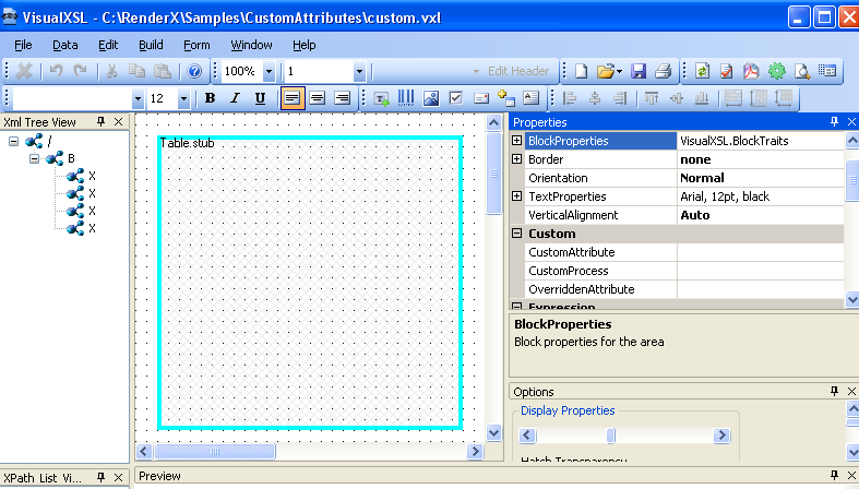
Figure 7.24. CustomAttributes file, with table with cyan border
-
In the Properties pane, under Custom, select
CustomAttributes.Change the left border to
2px redand the top border to2px blueby entering the following value:border-left=”solid 2px red” border-top=”solid 2px blue”. Note the space separating the two values. -
In the Properties pane, under Custom, select
OverriddenAttribute.Remove the rest of the (
cyan) border altogether by entering the following value:border. -
Do either Build Preview or Build Create PDF. The updated frame's left border is red, top is blue and nothing remains of the cyan. The updated frame can be seen in the Preview pane.
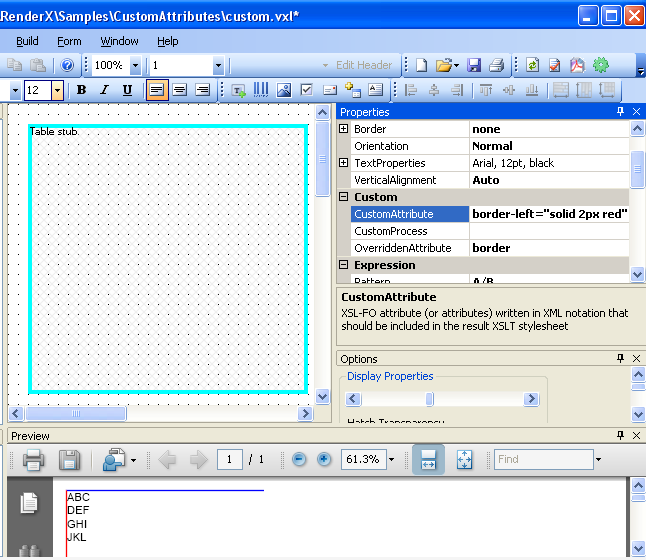
Figure 7.25. Preview, showing updated frame, with red left border, and blue top border
7.9. Example of Creating PDF Form
VisualXSL 2.3 and upper versions provide a new, easy to use method of creating fillable PDF Forms. Now the procedure of creating a PDF Form is the same as creating any PDF document.
This example shows how a simple PDF form can be created and submitted to the server. To submit the form, you need to have access to a server, where the data is submitted and handled.
Procedure 7.5. To create a PDF Form
-
In the
Samples/Registration Formfolder openregistration_form.vxlfile via VisualXSL.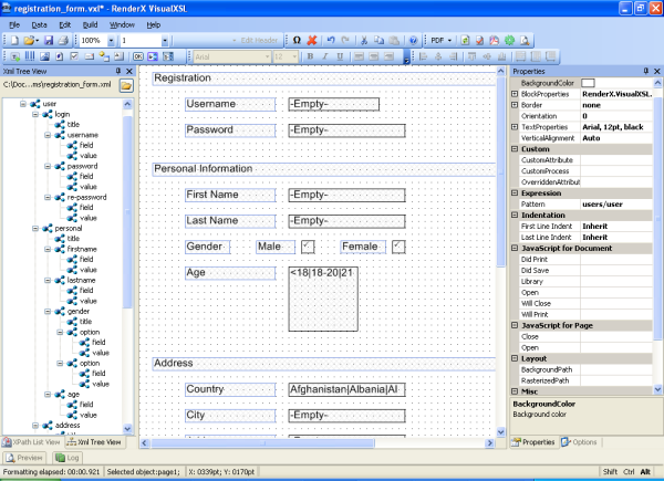
Figure 7.26. Registration Form
-
There are several frames, which assemble a simple registration form. The first part has a title called
Registration, which contains two pairs of fields (each pair contains two fields in front each other). In this example all the pairs contain a usual text field and a fillable field (e.g. fillable text frame, checkbox, listbox, ...). Here we will pay attention to the fillable fields; more information about Text Fields can be found at 5.4 Text Frame.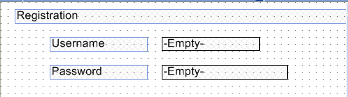
Figure 7.27. Registration Form
-
Username- fillable text field. To create a fillable text field add a Text Frame to the Layout and set its Treat as Field property totrue(Treat as Fieldis located in the Form Fields section of the Properties pane). VisualXSL sets a default value for the Name property, but as we need to handle the submitted data on the server, we should give names for the submitting frames. So, the name of the Username field is set tousername. For all other form fields we set individual Name properties. We can also give the maximum allowed length of the entered text: navigate to the Properties pane, Form Fields section, Max Length property, for this field its value is15. Besides, usually Username is a required field, to emphasis that, we gave to Required property thetruevalue. -
Password- password field. Password field is created from a fillable text field. To create aPassword, create a fillable text field, like theUsernamefield and set its Password property totrue -
The second part of the form is called
Personal Data. The first two pairs areFirst NameandLast Name. They are created just like theUsernamefield.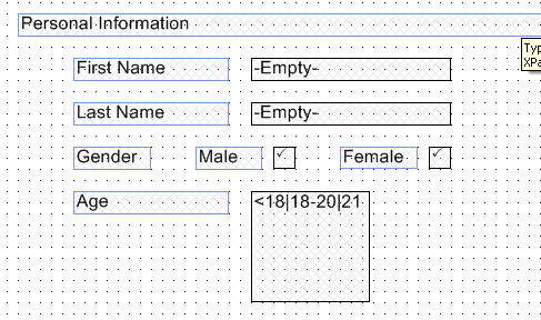
Figure 7.28. Registration Form
-
Then comes
Genderfields, which is a group of Radio Buttons. There are used text frames and two radio buttons. Detailed information about how to create Radio Buttons see 7.3. Example of Using Radio Buttons. -
The last pair of this section is
Age. The user is suggested to select his/her age from the given intervals, which are presented as options of a List Box. To create a List Box select the XML node from which you wish the options to be generated and click Add List Box. The values are taken from the source XML (registration_form.xml). VisualXSL sets the current XML node's inner text as theList Box'sValues. Options are generated from theValuesproperty on the Properties pane, its values are separated bySeparatorproperty. Here the age intervals are separated by|and as theSeparatorproperty is|, we get the desired intervals -<18,18-20,21-25,26-30,31-40,>40. -
Addresssection contains information about the user's address and consits of three pairs of fields.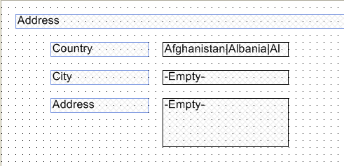
Figure 7.29. Registration Form
Country- Combo Box containing a list of countries. To create a Combo Box select the XML node from which you wish the options to be generated and click Add Combo Box. The values are taken from the source XML (registration_form.xml). VisualXSL sets the current XML node's inner text as theCombo Box'sValues. Options are generated from theValuesproperty on the Properties pane, its values are separated bySeparatorproperty. Here country names are separated by|and as theSeparatorproperty is|, we get the desired intervals -Afghanistan,Albania,Algeria, etc. . -
City- Fillable Text field. -
Address- Fillable Text field, designed for the user to write his/her address (Street, building, apartment, etc.). The only difference from other fillable fields is that it is multiline, that is - it can contain more that one line. To enable this feature set the Multiline property in the Properties panetrue. -
The
Signsection contains a Text Frame and a fillable Check Box, that is a Check Box, which Treat as Field property is settrue.
Figure 7.30. Registration Form
-
At the bottom of the form there are 2 Buttons - Reset and Submit.
Reset- this type of Button is used to reset all the fields to their default values. To create aResetbutton, add a Button, in the Properties pane set its Button Type propertyReset. Reset affects only the fields, which names are included in the Fields property (space deliminated list); or if it is left blank, all the fields of the document are affected. As in this example Fields property is left blank, all the fields are affected.
Figure 7.31. Registration Form
-
Submit- this type of Button is used to submit the form data to the server. To create aSubmitbutton, add a Button. The server's URL is set in the URL property of the Properties pane. By default it is the inner text of the XML node from which the button is created. In this example, it ishttp://localhost/forms/index.php, of course you may set your own server. The submittion method is set via Method property, its possible values arePOSTandGET. Here we usePOSTmethod. VisualXSL supports four formats for submitting:XFDF,FDF,PDFandHTML. Here we usedHTMLformat. The submitting format is changed from the Submit Format property on the Properties pane. -
After creating the form, generate the resulting PDF document, fill the form and click Submit button. The form data will be sent to the server, which Url is given to the
Submit Button'sUrlproperty. This sample includesvisualxslforms/index.phpfile, which is a simplePHPfile to show all the data sent to the server. You can copy - paste it to your php server, to see how the sample works.Note: Adobe Acrobat Reader does not read HTML format, and as in this example we use HTML to show the submitted data, you are strongly recommnded to use either Preview window or your web browser.
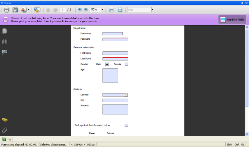
Figure 7.32. Registration Form